Build a Smart AHO Headlight Controller for Your Motorcycle with ESP32-C3 and ESPHome
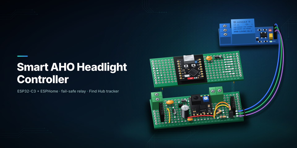
Most motorcycles sold in India since April 2017 come with Automatic Headlamp On (AHO): the headlamp lights up with the engine and stays lit. This post documents how I built a small, fail-safe controller that sits between the bike's harness and the headlamp. It reads the high-beam and low-beam wires, switches the headlamp through a relay, and talks to Home Assistant through ESPHome. A Google Find Hub tracker is the last phase.
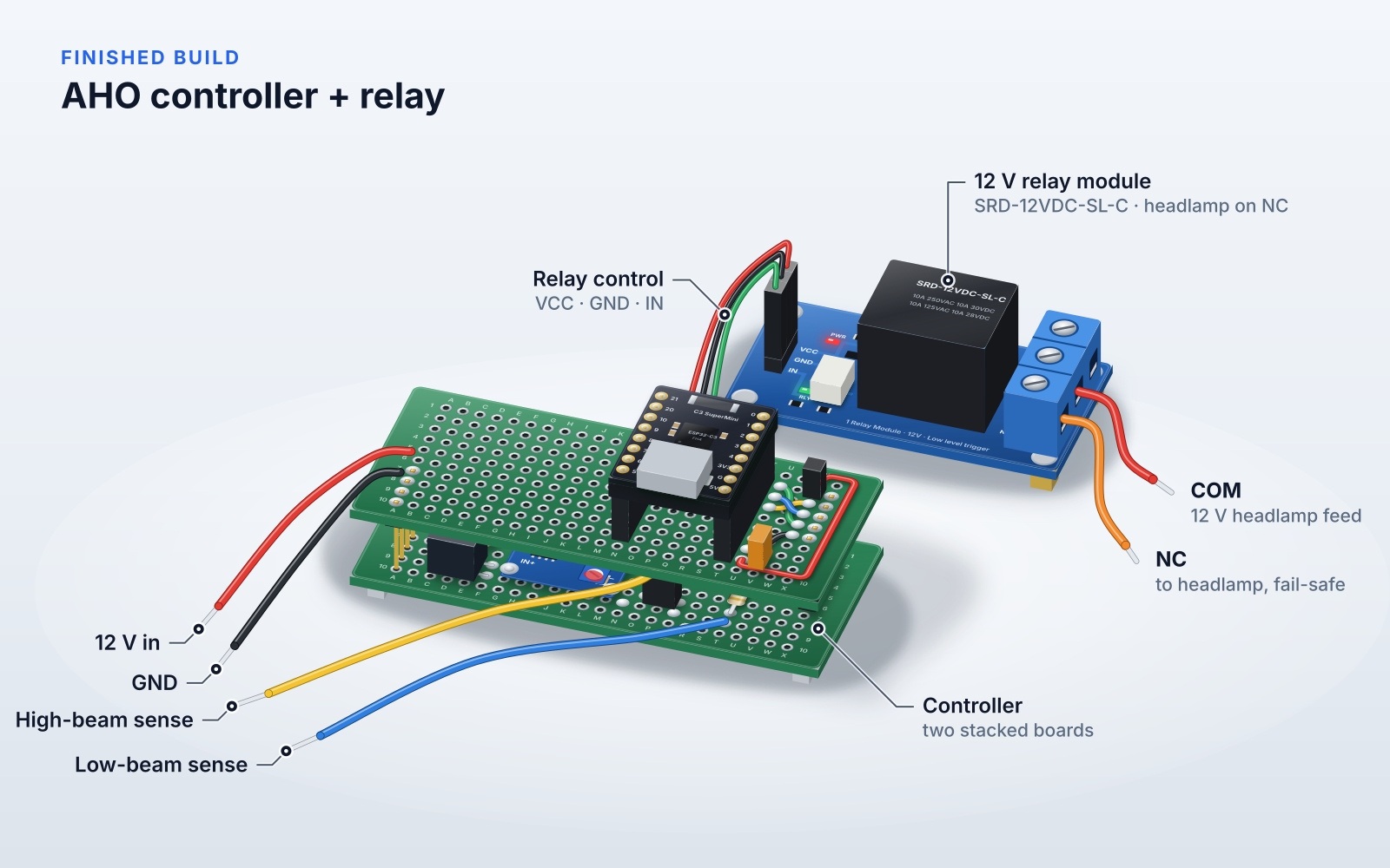
It is written so you can reproduce it with a soldering iron, a multimeter and a 3×7 cm perfboard. No custom PCB is needed. Every schematic and board layout below is a real drawing from my build.
Read this first: legal and safety notes
- AHO is a regulatory feature. New two-wheelers sold in India after April 2017 must have it, and a draft rule would make it low-beam only from April 2028. I am not a lawyer. Check what applies to your bike and your state before you change how your headlamp behaves. The firmware below is a reference. You can set it to keep the light on all the time.
- The design fails safe. The headlamp runs through the relay's normally-closed (NC) contact, so a dead ESP32, a crash or a blown fuse leaves the headlamp on.
- 12 V on a bike is not a clean 12 V. The protection stage in Phase 1 is not optional decoration.
- Never plug USB in while the bike is powering the board. Flash on the bench with the bike disconnected.
What you are building
- An ESP32-C3 controller powered from the bike's 12 V line, which is only live when the bike is on.
- A relay that switches the headlamp through its NC contact.
- Two voltage-divider inputs that read the high-beam (HB) and low-beam (LB) wires.
- ESPHome firmware: a relay switch, beam-state sensors and a hold the pass switch for 3 seconds toggle.
- Home Assistant integration for free, because ESPHome exposes everything as entities.
- Phase 4: a Find Hub tracker for the bike.
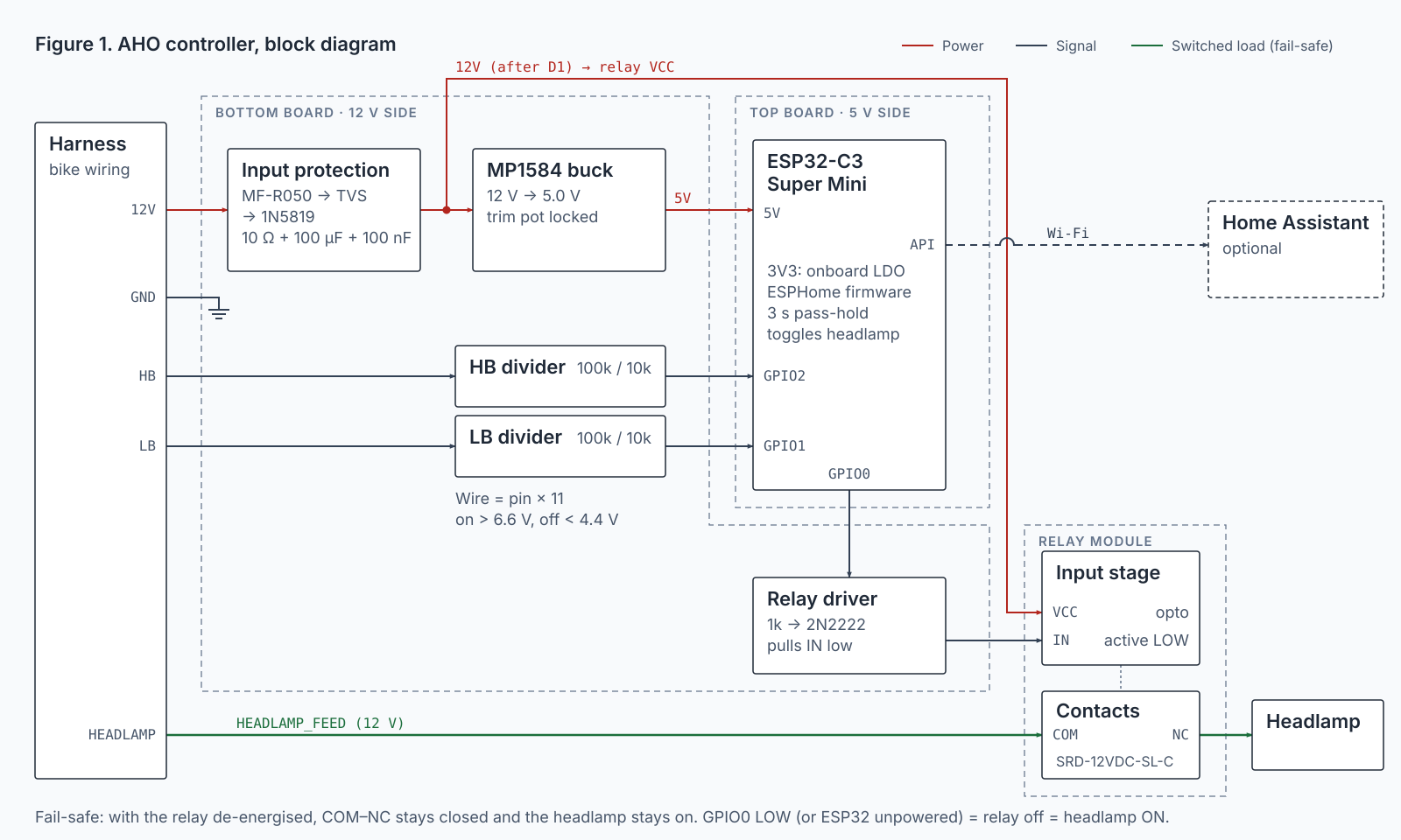
The bike side has four wires available: ground, low beam, high beam and the 12 V / 10 A headlamp line. The controller is powered from that same 12 V line, so it only runs when the bike is on and the bike's own start-up behaviour (including crank delay) still applies.
Why the NC contact matters
| ESP32 relay pin | Relay coil | NC contact | Headlamp |
|---|---|---|---|
| LOW (boot, crash, ESP dead) | Off | Closed | ON |
| HIGH | On | Open | OFF |
One trade-off: with NC wiring the headlamp flashes on for roughly half a second to a second while the ESP32 boots. That is unavoidable, and it is the price of failing safe.
Parts list
| Part | Notes |
|---|---|
| ESP32-C3 Super Mini | Powered through its 5V pin (the onboard LDO makes 3.3 V) |
| Mini MP1584 buck module | Set to 5.0 V before connecting anything. Input max 28 V |
| 12 V 1-channel relay module | Low-level trigger, optocoupler, SRD-12VDC-SL-C relay (10 A) |
| 2N2222 NPN transistor | Relay driver |
| 1N5819 Schottky diode ×2 | D1 reverse-polarity protection, plus one on the 5 V feed to the ESP32 |
| TVS diode, P6KE18A / P6KE20A | See the TVS table below |
| Polyfuse MF-R050 | 500 mA hold, on the 12 V input |
| Resistors | 100 kΩ ×2, 10 kΩ ×3, 1 kΩ ×1, 10 Ω ×1 |
| Capacitors | 100 µF electrolytic rated 25 V or more (C1), 100 nF ceramic ×2 |
| 3×7 cm double-sided perfboard ×2 | Stacked |
| 2.54 mm headers | Female on the bottom board, male on the top board |
| Screw terminal, hookup wire, hot glue | Thick wire for the headlamp path. Thin wire for signals |
Phase 1: Design the circuit
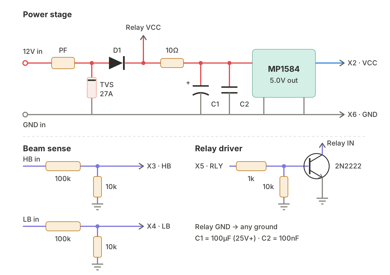
The whole circuit is four small blocks. Here is the full schematic, then each block and why it exists.
1. Input protection
A bike's electrical system sees spikes from the ignition and from the charging system. Industry notes on automotive transients and load dump describe pulses far above the 14 V a running bike normally shows. The chain, in order:
- Polyfuse (500 mA hold): limits fault current. The relay coil, the buck module and the ESP32 together draw well under this.
- TVS diode across 12 V and ground: clamps spikes.
- 1N5819 (D1) in series: blocks reverse polarity.
- 10 Ω + 100 µF + 100 nF: a small RC filter that soaks up fast spikes the TVS lets through, before the buck module.
Choosing the TVS. The standoff voltage must be above the highest voltage the bike runs at (around 14.5 V), or the TVS conducts all the time and cooks. The clamp voltage should stay below what the buck module can survive. The MP1584 is rated for a 4.5 V to 28 V input. These values come from the standard P6KE datasheets:
| Part | Standoff | Max clamp | Verdict |
|---|---|---|---|
| P6KE12CA | 10.2 V | 16.7 V | Do not use. It conducts at normal running voltage |
| P6KE18A | 15.3 V | 25.2 V | Good |
| P6KE20A | 17.1 V | 27.7 V | Ideal |
| P6KE27A | 23.1 V | 37.5 V | Acceptable with the 10 Ω filter, but the clamp is above the buck's rating |
| P6KE36CA | 30.8 V | about 50 V | Does not protect the buck from 28 to 34 V events |
My drawings show a P6KE27A. If you want to stay fully inside the MP1584's rating, pick P6KE18A or P6KE20A.
2. Power: 12 V to 5 V
A mini MP1584 buck module steps 12 V down to 5.0 V. Two habits that saved my boards:
- Set the output to 5.0 V on the bench before the module is connected to anything, then lock the trimpot with glue or nail polish.
- Feed the ESP32-C3 through its 5V pin, not the 3V3 pin. The onboard regulator tolerates a bit of ripple or drift. A second 1N5819 on that feed leaves about 4.6 to 4.7 V at the pin.
3. Reading the beam wires
Each beam wire goes through a 100 kΩ / 10 kΩ divider. The pin sees the wire voltage × 10/110, about 0.0909. A 12 V beam gives roughly 1.1 V and a 14.4 V beam about 1.3 V, well inside the ADC range. A divider only draws about 0.1 mA. In firmware the reading is multiplied by 11 to get wire volts back.
| State | Wire | Pin |
|---|---|---|
| Beam on (threshold) | above 6.6 V | above 0.6 V |
| Beam off (threshold) | below 4.4 V | below 0.4 V |
| Normal running | 12 to 14.4 V | 1.1 to 1.3 V |
4. Driving the relay
Common 12 V relay modules use a low-level trigger through an optocoupler. A 3.3 V GPIO cannot drive that input directly: it would never turn the relay fully off and it back-feeds the GPIO. A 2N2222 solves it by pulling the module's IN pin to ground. A 1 kΩ base resistor and a 10 kΩ base pull-down keep the relay released while the ESP32 boots.
The thick headlamp wires never touch the perfboard. They go straight to the relay terminals.
Phase 2: Build it on perfboard
Two 3×7 cm boards are stacked. The bottom board is the 12 V side (protection, buck, dividers, driver) and the top board carries the ESP32-C3. They connect through a five-pin header, with female pins on the bottom board and male pins on top.
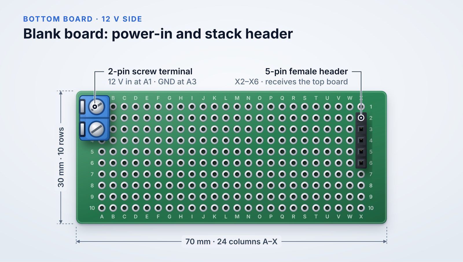
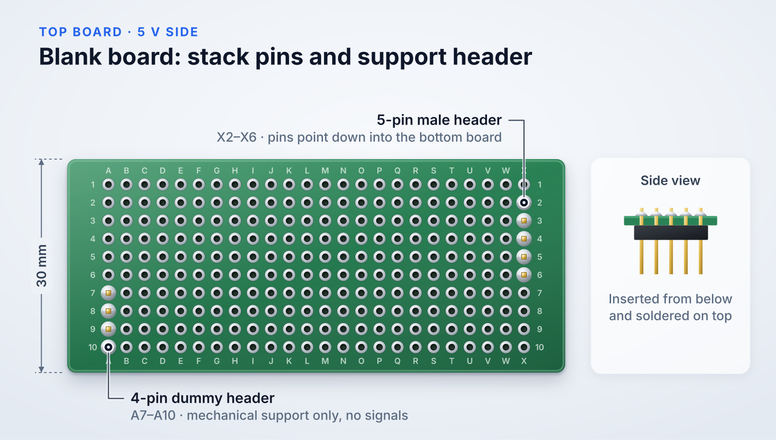
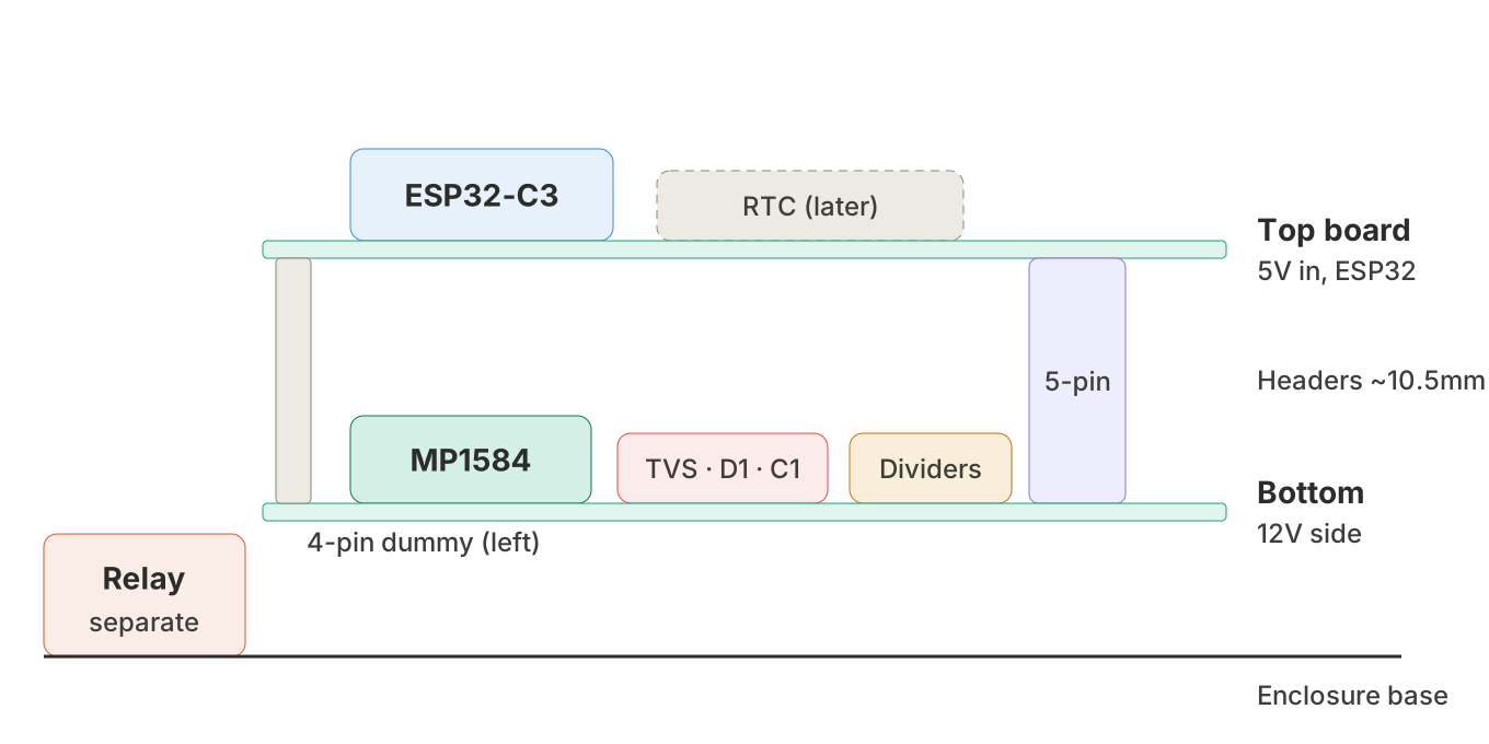
| Pin | Signal | ESP32-C3 |
|---|---|---|
| X2 | 5 V from MP1584 | 5V |
| X3 | High beam sense | GPIO2 |
| X4 | Low beam sense | GPIO1 |
| X5 | Relay drive | GPIO0 |
| X6 | Ground | GND |
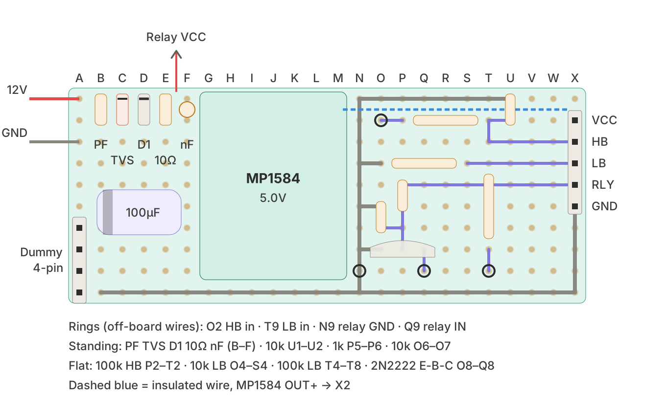
Below are the two halves, hole by hole. Red is the 12 V path, grey is ground, purple is signals and the dashed blue line is an insulated wire from the buck's OUT+ to header X2.
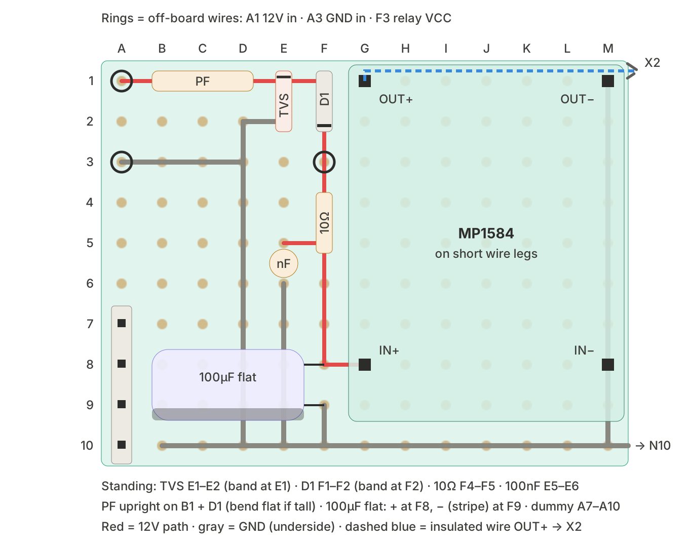
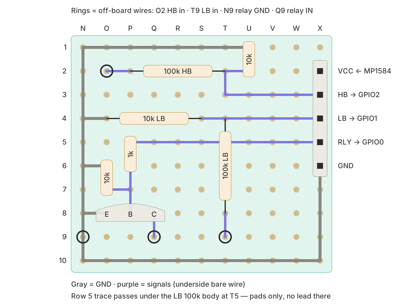
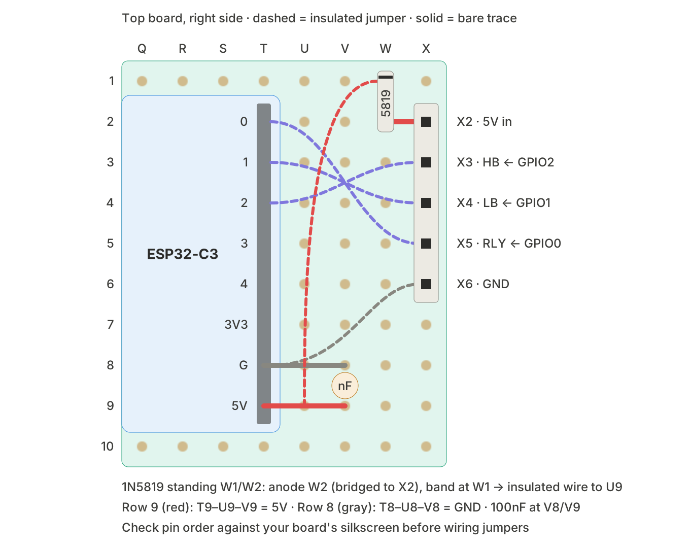
Keep the ESP32 antenna end of the top board clear of other parts. Check the ESP32-C3 pin order against your board's silkscreen before wiring the jumpers.
Soldering order
- Ground bus and rails
- Resistors (flat ones first, then standing)
- Diodes and TVS (check the bands)
- 100 nF capacitors
- 2N2222 (check emitter, base, collector with the multimeter diode mode)
- 100 µF capacitor laid flat, stripe to ground
- MP1584 (output already set to 5.0 V)
- Signal traces and insulated jumpers, then off-board wires
- Headers last
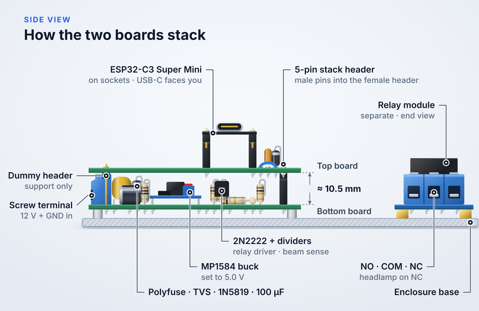
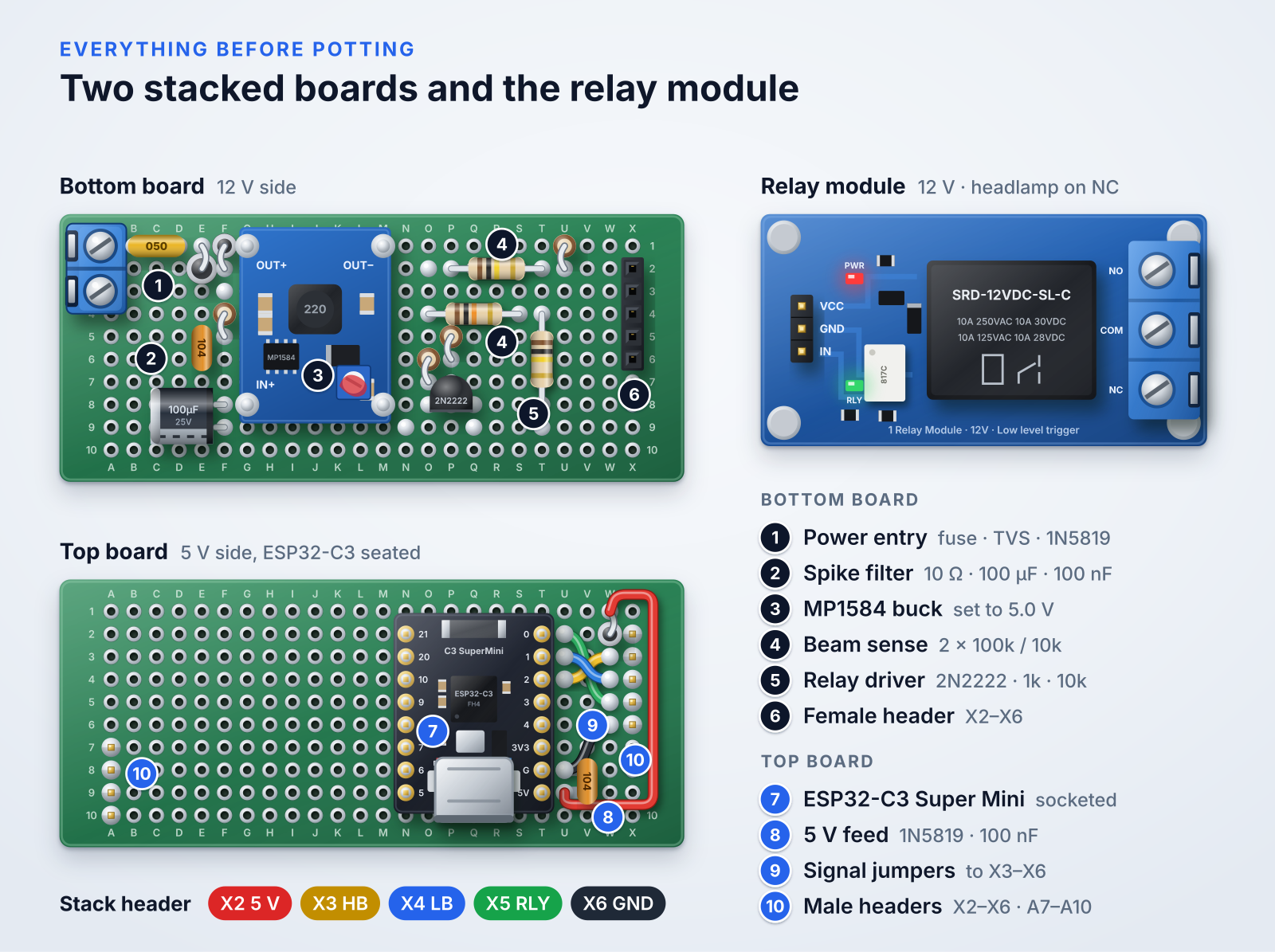
Test before you trust it
Power stage (bench supply or 12 V adapter):
- Resistance between 12 V and GND is not near 0 Ω.
- About 11.6 V at the node after D1, slightly lower after the 10 Ω.
- Set the MP1584 to 5.0 V with nothing connected, then lock the pot.
- Swap the input polarity briefly: output stays at 0 V and nothing gets warm.
- The capacitors stay cool after a minute.
With the top board stacked but the ESP32 not inserted, measure at the ESP socket holes:
| Socket hole | Expected |
|---|---|
| 5V pin | about 4.6 to 4.7 V (after the 1N5819) |
| 3V3 pin | 0 V |
| HB and LB pins | about 1.1 to 1.35 V with the beam on, about 0 V off |
| Relay pin | 0 V |
Continuity, power off: X2 to GND and 12 V to GND must not short. X3 to X4 should read about 20 kΩ (two 10 kΩ pull-downs); much lower means a solder bridge. 12 V to X3, X4 or X5 should read very high resistance.
Potting
Once everything tested fine, I potted the relay and the board stack separately in hot glue and joined them with a short cable. An enclosure with cable glands is still on my list.
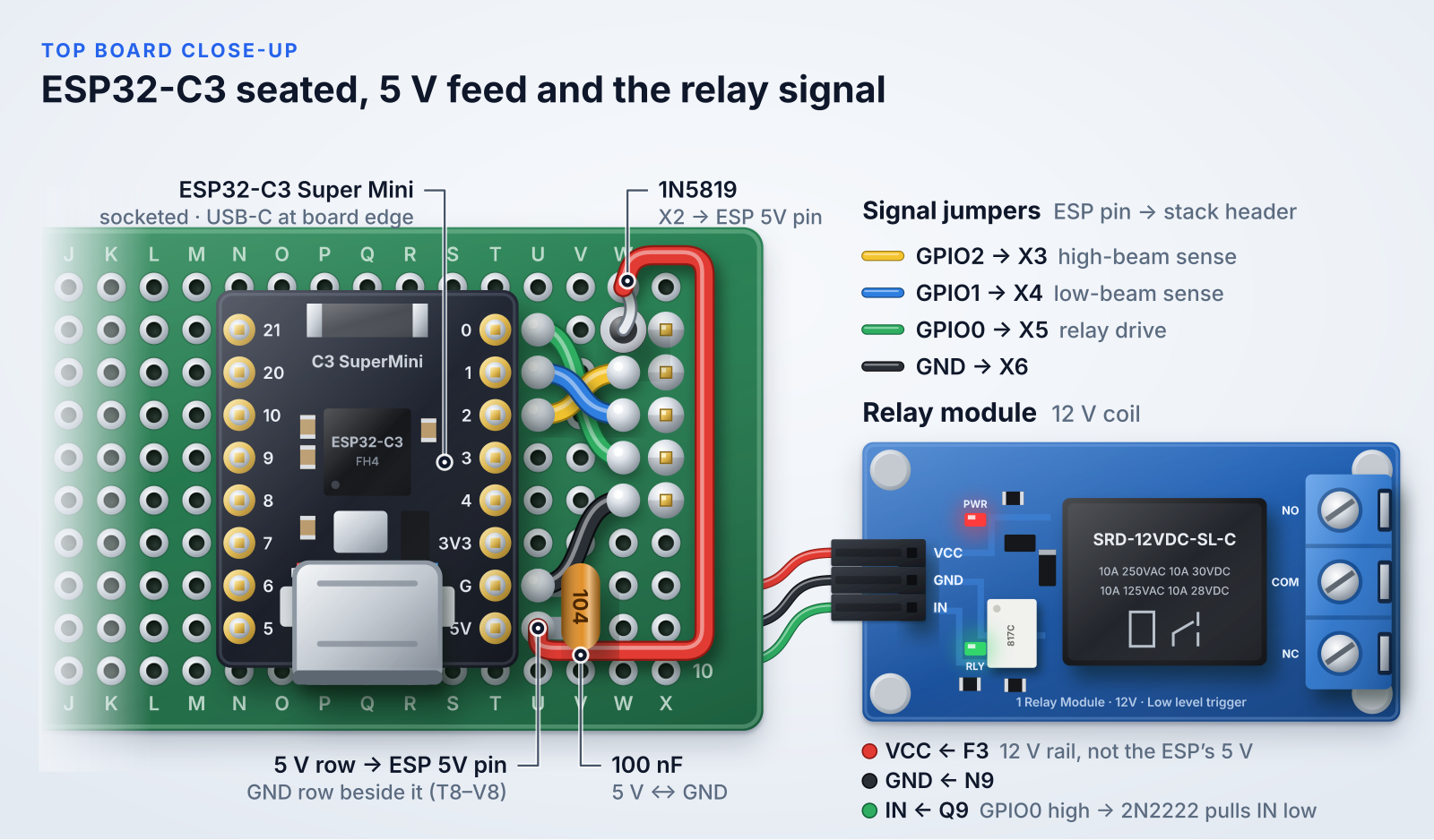
Phase 3: The ESPHome firmware
ESPHome turns a few lines of YAML into firmware and exposes the result to Home Assistant. You need the ESPHome dashboard (I use the Home Assistant add-on) and a USB-C cable.
How the config works
- Relay: GPIO0 is a GPIO switch with
inverted: true, so that switch ON means the headlamp is ON (the relay coil is released). - Beam sensors: two ADC sensors read the dividers every 100 ms, a three-sample moving average smooths them, and a ×11 multiplier turns the pin voltage back into wire volts.
- Hysteresis:
analog_thresholdturns a beam ON above 6.6 V and OFF below 4.4 V, with a 50 ms debounce. - Pass-hold toggle: a template binary sensor is true while the pass switch is held. When the headlamp is on, a pass means HB and LB are both on, since the dipper switch alone gives HB only. When it is off, HB alone counts. After 3 seconds the headlamp toggles.
- GPIO2 is a strapping pin with a pull-up on ESP32-C3. The
on_bootlambda disables the internal pull so the divider reads correctly.
The relay's boot state comes from restore_mode. My reference config uses ALWAYS_OFF. The ESPHome switch docs list the other modes, such as ALWAYS_ON, RESTORE_DEFAULT_ON and RESTORE_DEFAULT_OFF. If you want the light on by default, pick one of those. Hardware-wise the headlamp is on whenever the ESP32 is not driving the relay, regardless of this setting.
Reference config
Create secrets.yaml with wifi_ssid, wifi_password, ap_password and ota_password. For a build without WiFi, delete the wifi, captive_portal, api and ota blocks and flash over USB.
# Bike AHO controller - ESP32-C3 Super Mini
#
#   GPIO2  <- High beam sense  (100k / 10k divider)
#   GPIO1  <- Low beam sense   (100k / 10k divider)
#   GPIO0  -> 2N2222 -> relay IN (HIGH = relay on = headlight OFF)
#
# Headlight runs through the relay's NC contact, so relay pin LOW = headlight ON.

esphome:
  name: bike-aho
  friendly_name: Bike AHO
  on_boot:
    priority: -100        # after all components are set up
    then:
      - lambda: |-
          gpio_pullup_dis(GPIO_NUM_2);
          gpio_pulldown_dis(GPIO_NUM_2);

esp32:
  board: esp32-c3-devkitm-1
  variant: esp32c3
  framework:
    type: esp-idf

logger:
  hardware_uart: USB_SERIAL_JTAG
  level: INFO

wifi:
  ssid: !secret wifi_ssid
  password: !secret wifi_password
  reboot_timeout: 0s      # don't reboot every 15 min when there is no WiFi
  ap:
    ssid: "Bike-AHO Fallback"
    password: !secret ap_password

captive_portal:

api:
  reboot_timeout: 0s

ota:
  - platform: esphome
    password: !secret ota_password

switch:
  - platform: gpio
    id: headlight
    name: "Headlight"
    pin:
      number: GPIO0
      inverted: true         # switch ON = GPIO LOW = relay off = headlight ON
    restore_mode: ALWAYS_OFF # headlight OFF at every boot (turn on with 3 s pass hold)
    icon: mdi:car-light-high

# Divider 100k/10k -> wire voltage = pin voltage x 11
sensor:
  - platform: adc
    id: hb_volts
    name: "High Beam Voltage"
    pin: GPIO2
    attenuation: 12db
    update_interval: 100ms
    unit_of_measurement: V
    accuracy_decimals: 1
    filters:
      - multiply: 11.0
      - sliding_window_moving_average:
          window_size: 3
          send_every: 1
      - delta: 0.3

  - platform: adc
    id: lb_volts
    name: "Low Beam Voltage"
    pin: GPIO1
    attenuation: 12db
    update_interval: 100ms
    unit_of_measurement: V
    accuracy_decimals: 1
    filters:
      - multiply: 11.0
      - sliding_window_moving_average:
          window_size: 3
          send_every: 1
      - delta: 0.3

binary_sensor:
  # Hysteresis: ON above 6.6 V on the wire, OFF below 4.4 V
  - platform: analog_threshold
    id: high_beam
    name: "High Beam"
    sensor_id: hb_volts
    threshold:
      upper: 6.6
      lower: 4.4
    filters:
      - delayed_on_off: 50ms

  - platform: analog_threshold
    id: low_beam
    name: "Low Beam"
    sensor_id: lb_volts
    threshold:
      upper: 6.6
      lower: 4.4
    filters:
      - delayed_on_off: 50ms

  # Pass-hold toggle: hold the pass switch for 3 s to toggle the headlight.
  - platform: template
    id: pass_held
    name: "Pass Held"
    lambda: |-
      if (id(headlight).state) {
        return id(high_beam).state && id(low_beam).state;
      }
      return id(high_beam).state;
    filters:
      - delayed_on: 3s
      - delayed_off: 200ms
    on_press:
      - switch.toggle: headlight
Flashing
- Disconnect the bike. Plug USB into the ESP32-C3 only.
- Install the config from the ESPHome dashboard (first flash over USB, later flashes over the air).
- Open the logs. With the board powered from 12 V on the bench, watch HB and LB change as you apply voltage to the sense inputs.
- Only then install it on the bike, with USB unplugged.
Test the pass-hold behaviour on the bike
- Low beam on: HB off, LB on.
- Dipper to high: HB on, LB off. If LB stays on, the pass signature will not work.
- Pass on low beam: HB on, LB on.
- Headlamp switched off, press pass: does HB read about 12 V? If it reads 0 V, the pass switch is fed from the line the relay cuts, and it can not turn the light back on (see the gotchas).
Gotchas I hit (so you do not have to)
- Reversed electrolytic cap. A 470 µF cap I soldered backwards overheated. The stripe goes to ground. I replaced it with a 100 µF part.
- A dead ESP32 after about 15 minutes. Its 3V3 rail was shorted internally. The likely causes were a probe or solder slip between two adjacent holes (12 V and the buck's 5 V output), trimpot drift while feeding the 3V3 pin directly, or a spike getting through. The fixes: feed the 5V pin, lock the pot, keep the 12 V and 5 V holes apart, add the series 1N5819, and only probe with power off.
- The second pass-hold never triggers. When the relay cuts the whole headlamp line, the HB and LB wires go dead too, so the controller cannot see the pass switch. The planned fix is to have the relay switch only the LB wire, so the pass and HB path stays powered (untested):
12V -> dipper/pass switch --+-- HB wire --------------> headlamp HB   (sense here)
                            |
                            +-- LB wire -> relay COM
relay NC --> headlamp LB (sense after relay)- HB pin stuck at about 1.5 V. A roughly 10 kΩ pull-up on the ESP32 pin fought the 9 kΩ divider and held the pin at about 1.57 V. Moving the input to a different pin fixed it.
- GPIO2 reading 3.3 V. Nothing in the config drives it. It is a strapping pin with a pull-up, and the
on_bootlambda releases the internal one. If it still reads 3.3 V, the pull-up is a resistor on your board. - LED headlamps can leak voltage onto the HB wire when LB is on. If you see that, add a 2 kΩ resistor from the HB wire to ground at the board input, or raise the thresholds.
Phase 4: Add a Find Hub tracker
Status: working. The controller above is built and running, and the tracker location now shows up in Home Assistant. This section covers how the tracker works and what to know before you set one up.
What Find Hub is
Find Hub (formerly Find My Device) is Google's network for locating devices. A tracker broadcasts a Bluetooth LE identifier, and nearby Android phones relay where they saw it. That is why the ESP32 itself does not need GPS or a SIM.
The tool: GoogleFindMyTools
GoogleFindMyTools by Leon Böttger re-implements parts of the Find Hub protocol. It can query your devices, decrypt their locations, and register custom trackers. The repository includes ESP32 firmware (ESP-IDF, in C) and a Zephyr firmware. The flow, as described by the project and by CNX Software's walkthrough:
- Run
main.pyon a computer and sign in to your Google account (it uses Chrome). - Press
rto register a new tracker, then follow the on-screen steps to get its key. - Build and flash the ESP32 firmware with that key.
- Run
main.pyagain to see the tracker and its locations.
A fork, GoogleFindMyToolsWebUi, adds a self-hosted web interface and can build firmware for ESP32 and ESP32-C3 from the browser. Treat both projects as community tools.
Caveats to know before you start
- It is experimental. It uses reimplemented, undocumented Google interfaces, so it can break when Google changes things. Early coverage mentioned having to re-register the ESP32 after about three days. Check the current README and issues to see whether that still applies.
- Protect the credentials file. The tool stores your authentication in
Auth/secrets.json. Anyone with it can query your devices, so keep it out of git and off shared machines. - Only track your own property, and read the firmware options about unwanted-tracking alerts carefully.
Ways to fit it on the bike
- Option A, a separate tracker board. A second ESP32-C3 running the GoogleFindMyTools firmware, powered from the bike's 5 V, hidden elsewhere on the frame. It keeps the headlamp controller simple and untouched.
- Option B, the same ESP32-C3. This is what I want in the long run: one board, one harness. The official firmware is a standalone ESP-IDF app rather than an ESPHome component, so this means porting its BLE advertising into ESPHome. I have not verified that this works yet.
The tracker location now shows up in Home Assistant. I will add the exact hardware, pin and power details to this post.
What is left on my list
- Swap the TVS for a P6KE18A or P6KE20A and fit the MF-R050 polyfuse.
- Settle the pass-switch feed (relay switching only the LB wire).
- Re-check the GPIO2 reading after the pull-up fix.
- Add 47 to 220 µF at the ESP32's 5V pin if WiFi causes brownout resets.
- Add a DS1302 RTC on the top board (columns B to L are free for it).
- A 3D-printed enclosure with cable glands, plus conformal coating on the joints.